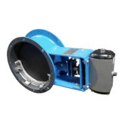
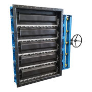
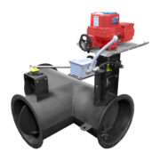
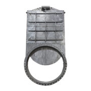
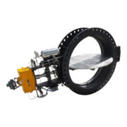
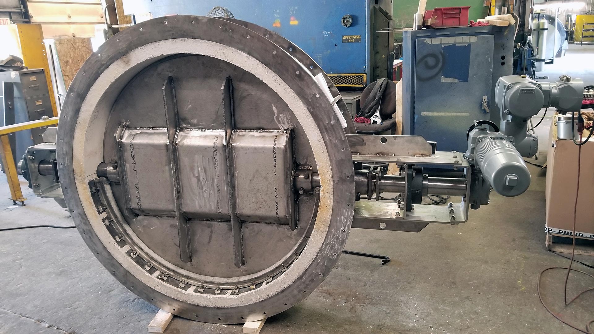
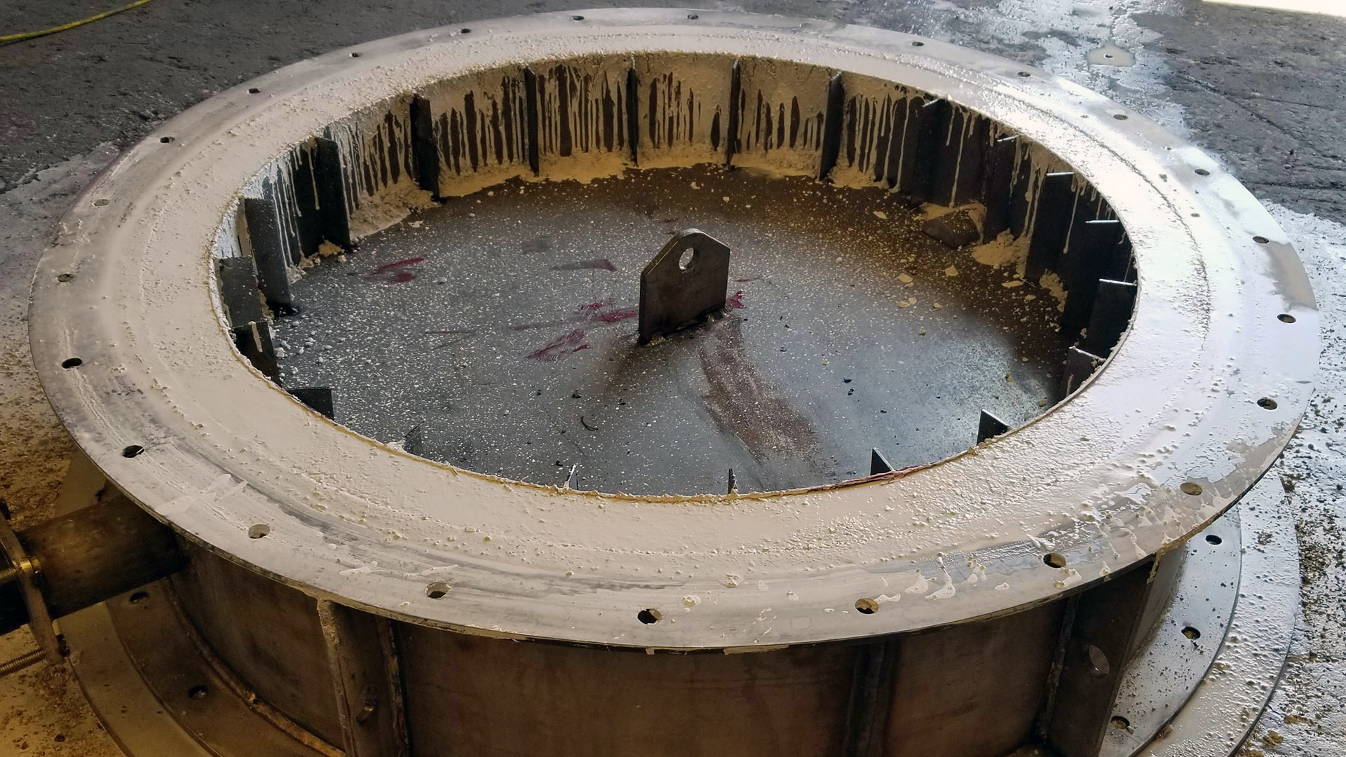
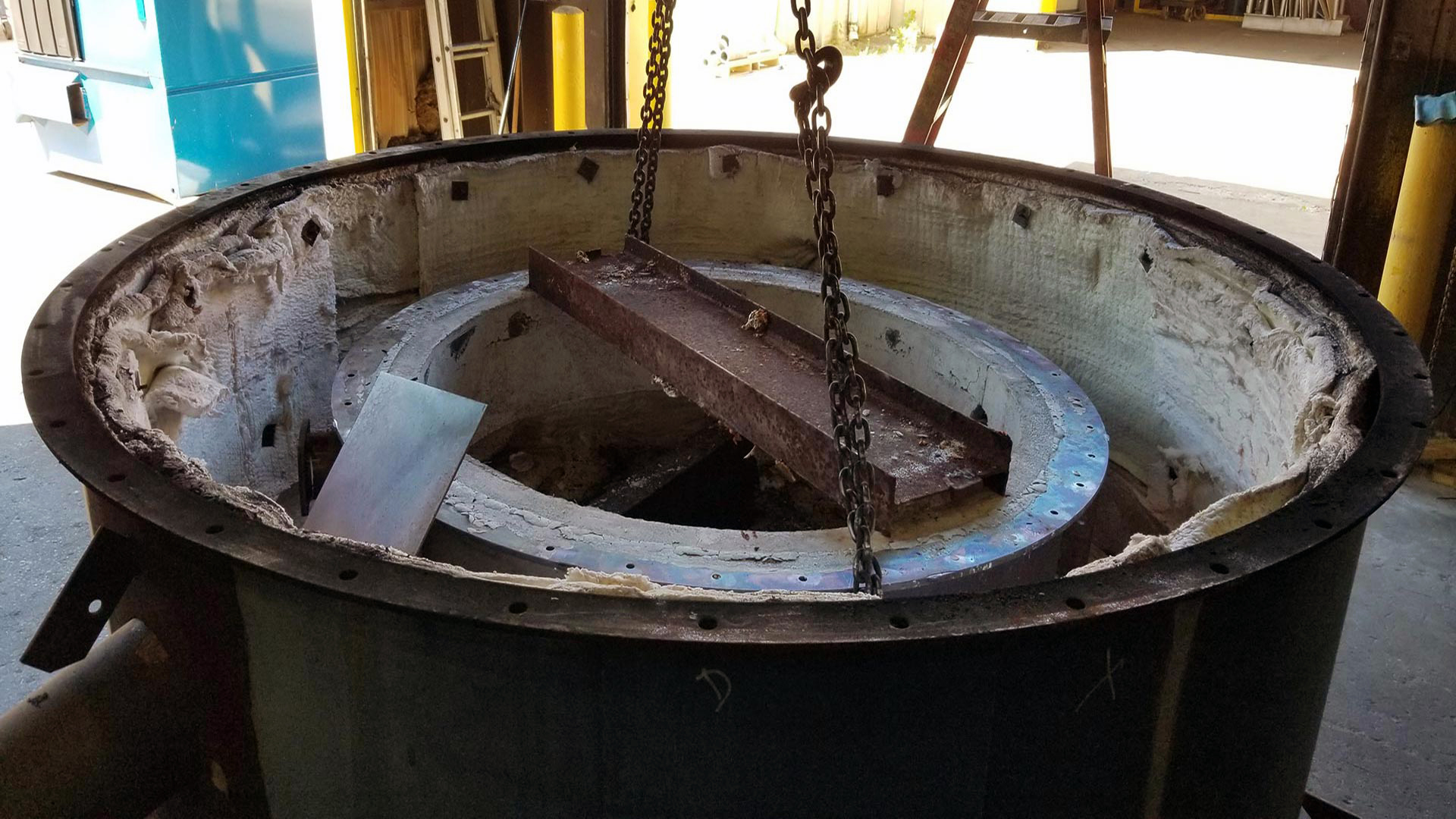
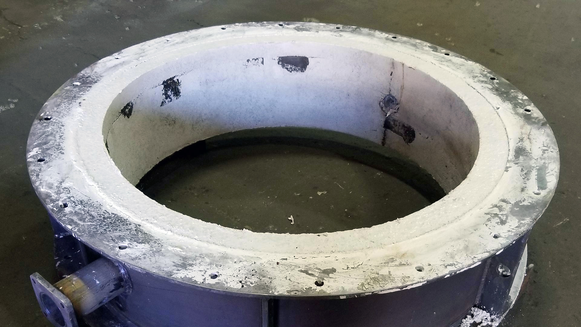
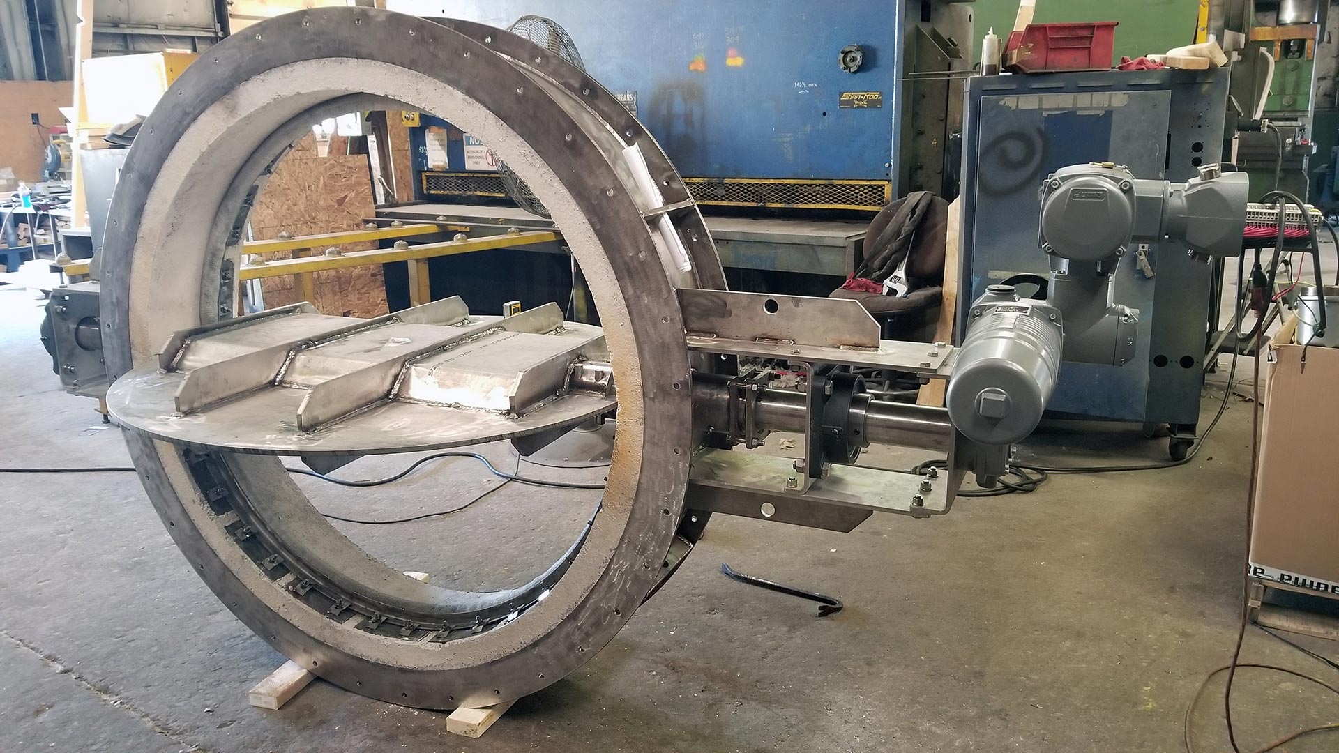
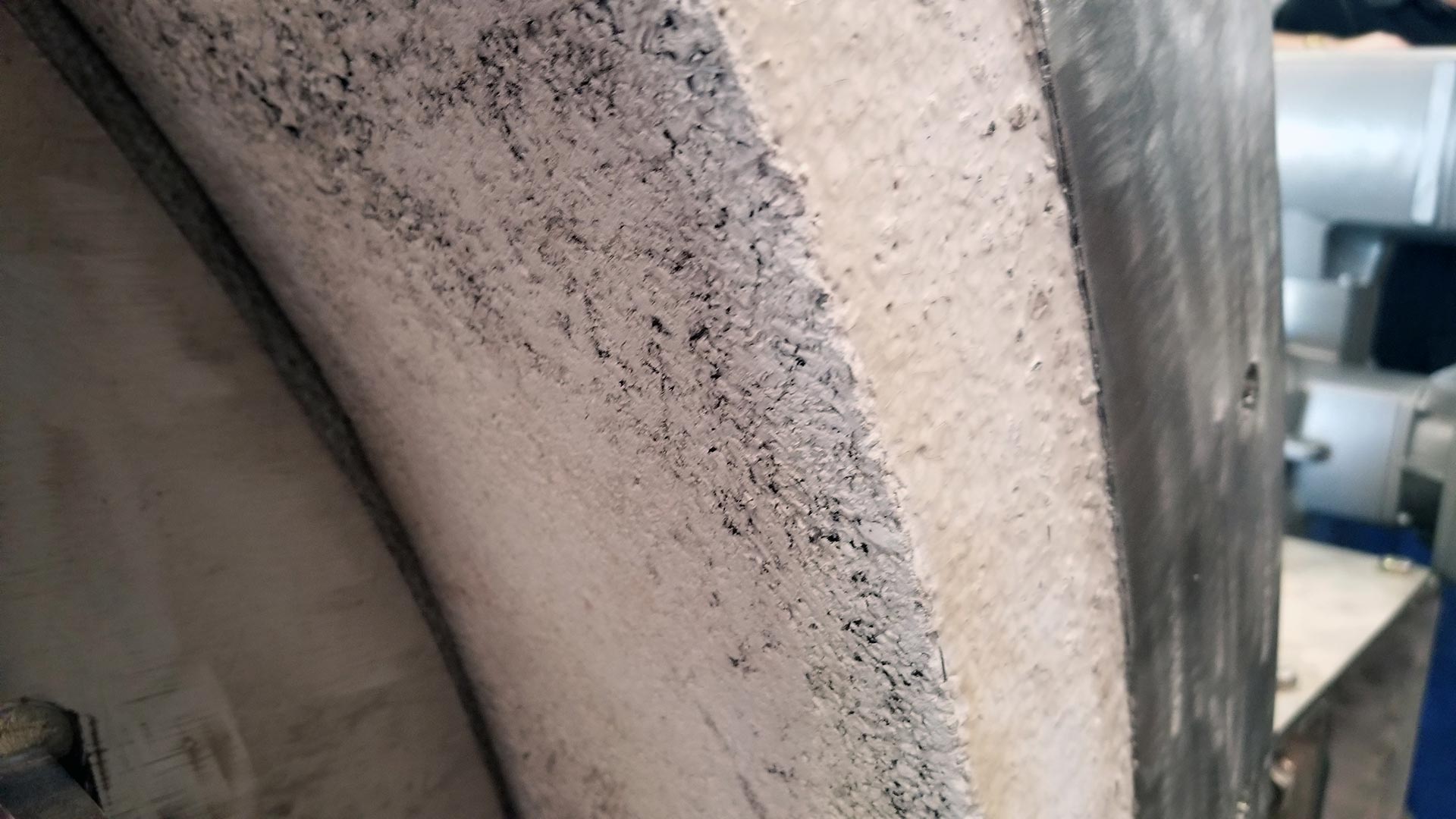
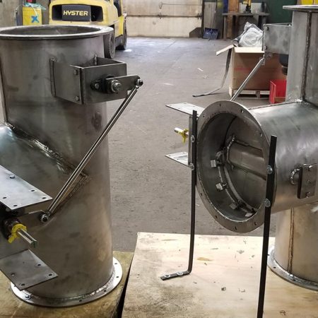
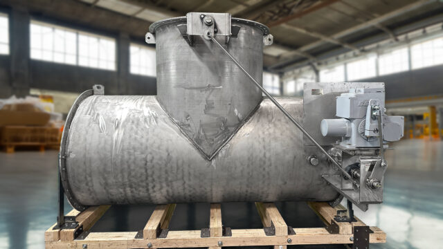
Elite Industrial Controls offers high temperature valve and damper designs to fit our customers wide range of applications. One of our Elite specialty valve types are our refractory lined dampers. Below are examples of various sized reduced refractory lined 2400 series dampers including a 1537mm (Ø60-1/2″) reduced to 1337mm (Ø52-5/8″) to a smaller 1150mm (45-1/4″) reduced to 950mm (37-13/32″) custom 2423-7-8-9 damper. Their application was for flue gas operating temperature of 871°C (1600°F) to maximum temperature of 1000°C (1832°F) at their main facilities in Canada. Our refractory technique and processes are detailed with additional QC inspections on various stages to ensure the refractory is set and cooked properly.
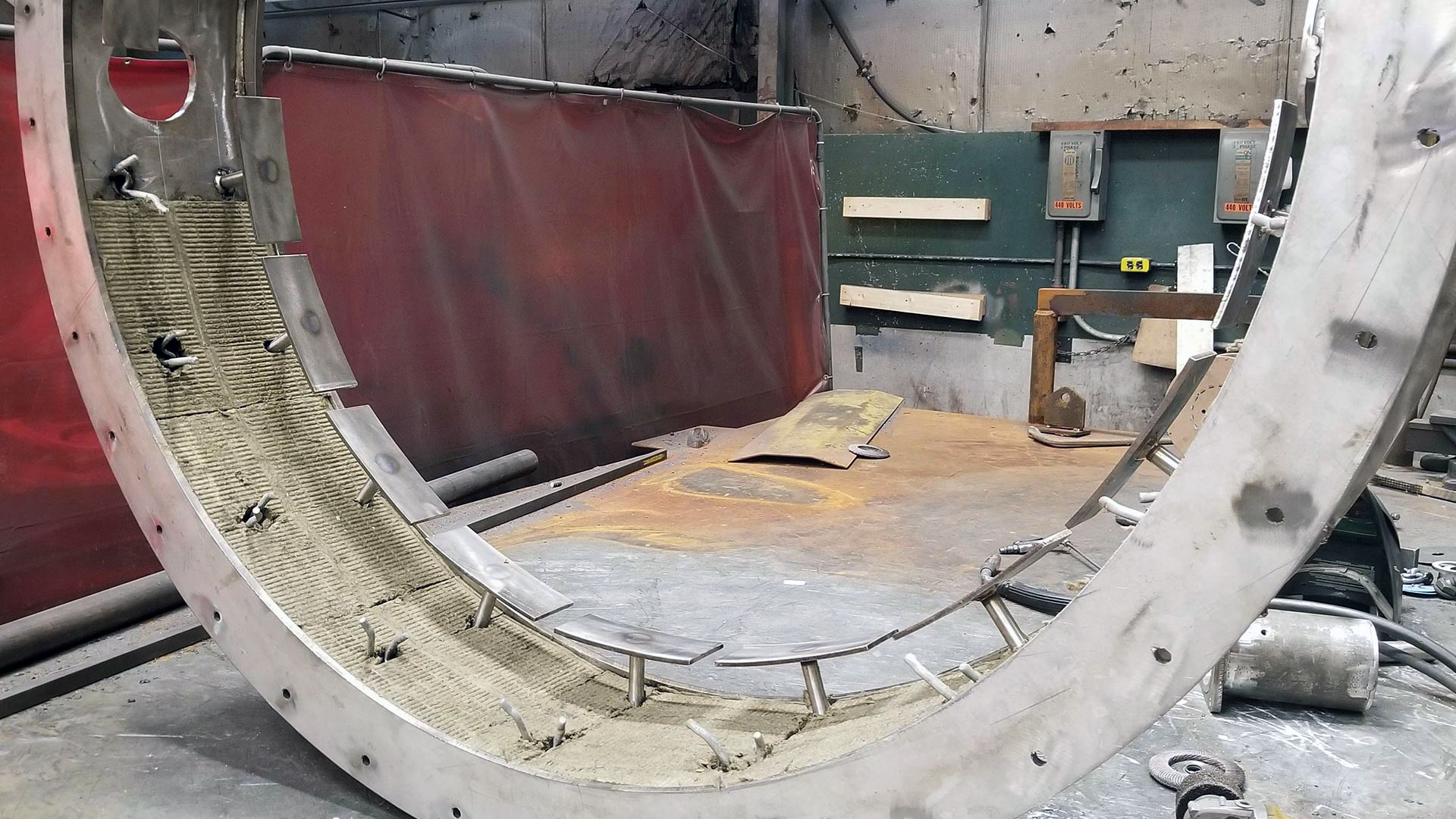
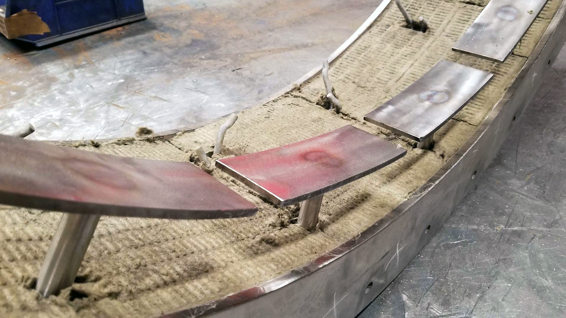
Our refractory lined dampers follow our standard valve design but include additional structural items to withstand high temperatures. High grade stainless steel standoff studs are welded into place with stainless steel stud plates rolled to the I.D. of the damper. On the opposite side of the standoff studs refractory anchors are welded to reinforce the structure and set in place. Finally insulation board is cut to size and stuffed into the lip of the damper assembly.
A false body & disc are created and welded together to form the reduced I.D. of the damper. The refractory is mixed accordingly to the quantity needed per damper size. Once mixed to contain a certain consistency it is poured into the created gap between the damper body and newly inner wall. Once filled to the top it is left to settle and add more refractory if needed to be filled to the rim. It is then leveled with a finishing tool to ensure the refractory does not stick past the designated damper face to face.
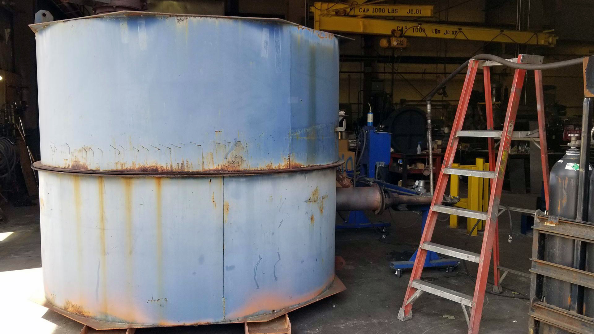
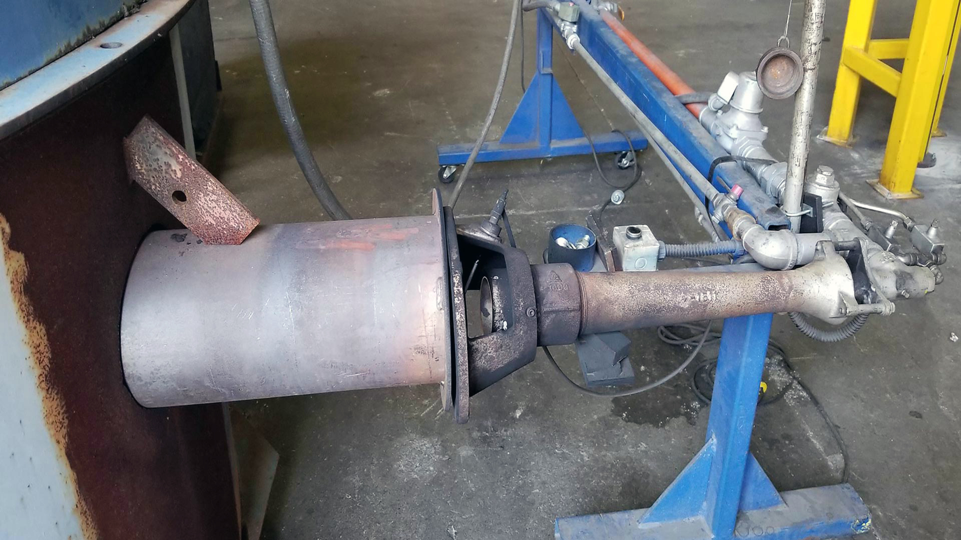
Once the refractory is settled and leveled accordingly the next step is cook. Each damper is then placed into our custom made furnace stacked on top of one another spaced equally apart. The dampers are then cooked over a 24 hour period increasing the temperature 50°F every hour up to 1200°F. After cooking the dampers are then set to cure at a minimum 24 hours before removal to ensure the refractory can withstand movement and the end result project application.
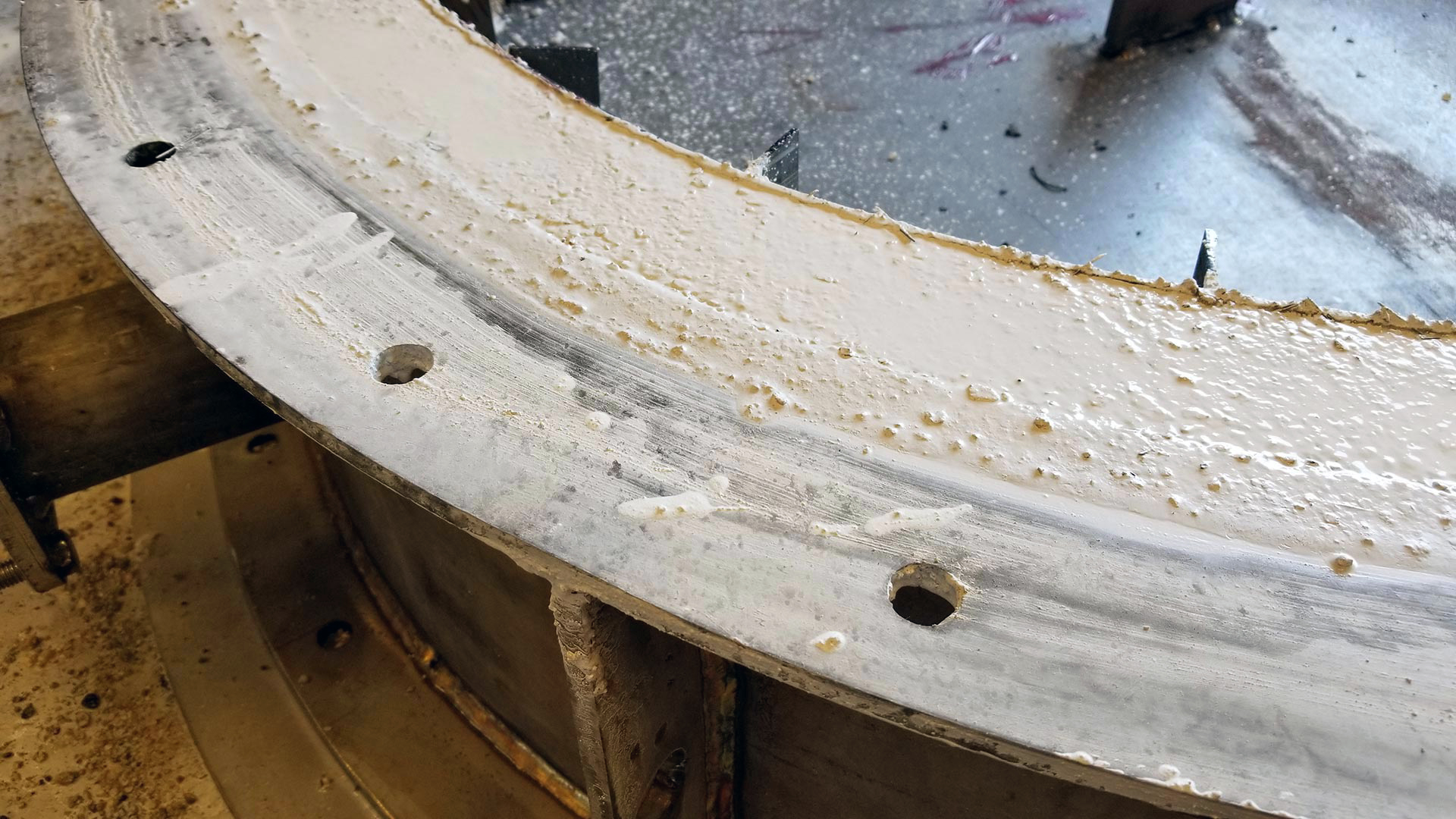
The dampers are then removed carefully so the refractory is not chipped or cracked in the process. The dampers are then cleaned up removing any excess refractory that has spilled or formed on the flanges. This can cause issues on damper installation allowing a secure seal on the face of the flange.
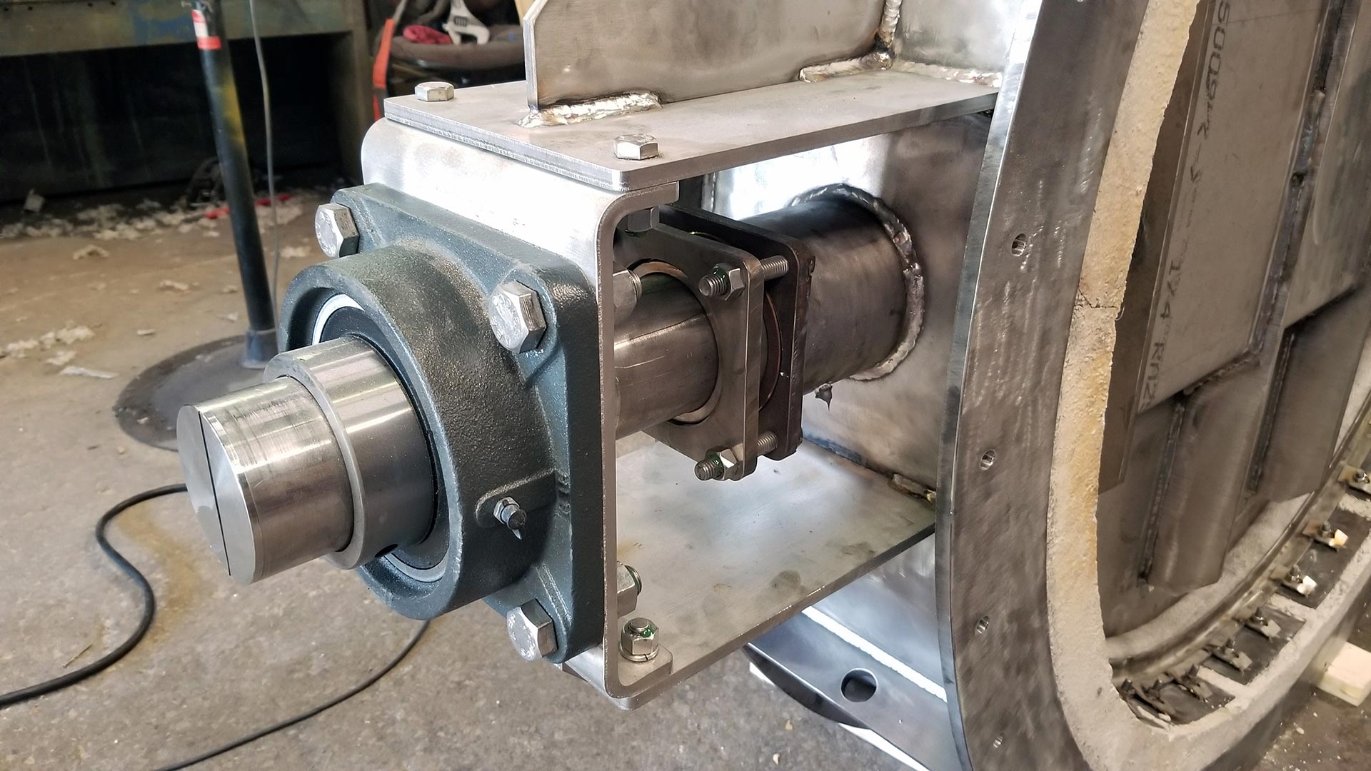
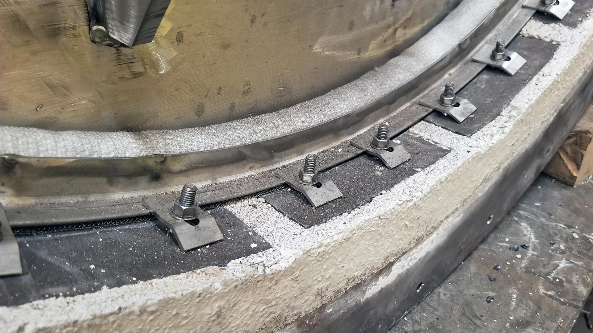
Standard damper assembly is continued installing the bracket legs both sides of the damper centering to the stuffing boxes. In this application, ball bearings are installed on both the power and blind side. Next the disc is placed ensuring it to clear the refractory edge without interfering. Disc hubs are preinstalled to the disc and welded in place. Shafts are then placed on the appropriate sides via disc hubs and taper pins installed. The previous installed stud plates are then used to weld in studs to install and hold the tadpole seat in place to secure a tight seal.
The damper is then moved into final assembly to install the customer specified actuation and perform a set amount of quality control inspections. Actuation is programmed and set to the appropriate fail position and adjusted to ensure the disc is applying enough pressure against the tadpole seat to guarantee the <1% estimated leakage based on maximum capacity. Once approved through QC the dampers are then crated to secure the refractory in place and prevent vibration/damage via shipping.

